
4.2.6 Module
The Modules area is available under Input. It provides controls for supported connected modules, including module configuration, addressing, information requests, readings, maintenance, and manual switching. The available tabs and controls depend on the connected hardware and configuration.
Connect to the SmartSampler2 before using module controls. SmartConfig2 normally loads the device configuration automatically after connection. Use Reload Settings only if automatic retrieval did not complete or you deliberately need to refresh the settings.
Articles
Master
The Master tab provides basic module-management functions.
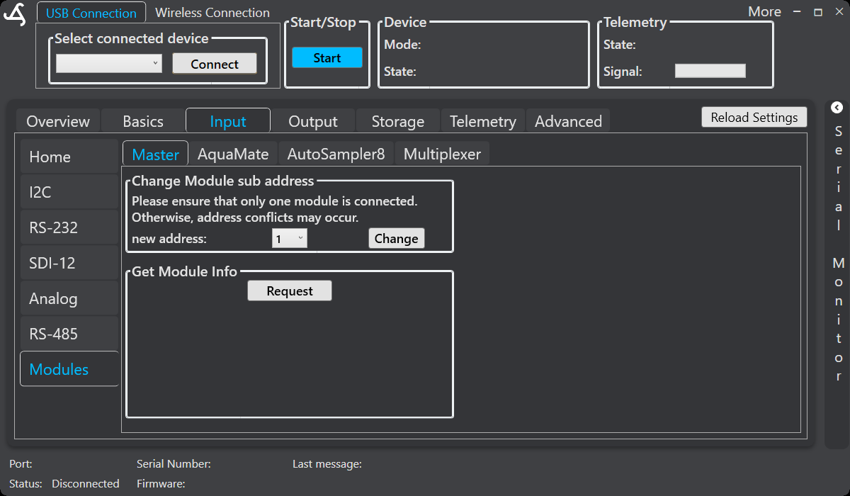
Change module sub-address
The Change Module sub address control assigns a sub-address to a connected module. If multiple modules share the same connection, each must have a suitable unique address.
Before selecting Change, ensure that only one module is connected. The on-screen warning states that address conflicts may occur otherwise. Select the required value in new address, then select Change.
Get module information
Use Request in the Get Module Info section to request information from the connected module. This is useful for confirming communication and checking that the intended module is responding.
AquaMate
The AquaMate tab provides connected-module settings, maintenance actions, and manual valve controls.
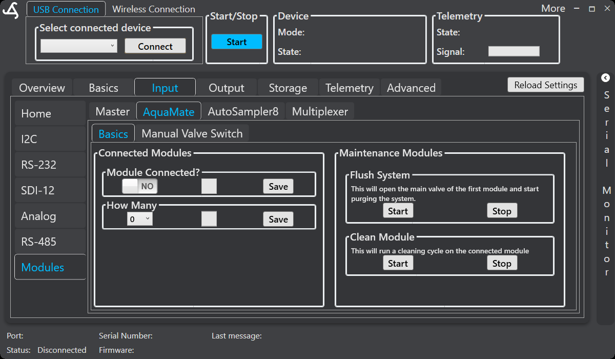
Connected modules
Use Module Connected? to indicate whether an AquaMate module is installed. Use How Many to select the number of connected modules. Select the corresponding Save button after changing each setting.
Maintenance modules
The Maintenance Modules section provides separate start and stop controls for supported maintenance operations.
Flush system
Flush System: Start starts a purge operation by opening the main valve of the first module. Use Flush System: Stop to stop the operation.
Before starting, confirm that the tubing and discharge path are connected correctly and that discharged fluid can be handled safely.
Clean module
Clean Module: Start starts a cleaning cycle on the connected module. Use Clean Module: Stop to stop the operation. Use these controls during setup, cleaning, or a controlled service visit rather than during normal unattended sampling.
Manual valve switch
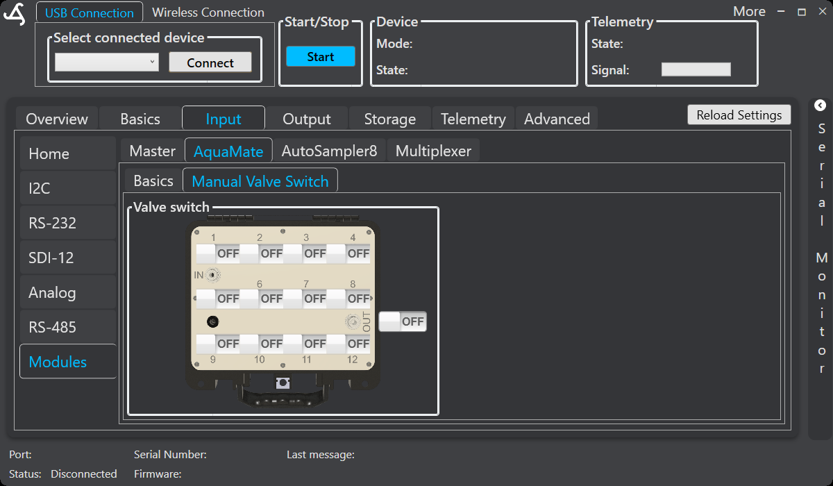
The Manual Valve Switch tab shows valve positions 1 through 12 and an overall switch control. Use the individual controls to switch supported valve positions on or off for installation checks, diagnostics, and maintenance.
Do not use manual valve control while an automated program is running. Check tubing, sample containers, and discharge paths before changing a valve state.
AutoSampler8
The AutoSampler8 tab provides configuration, data-request, live-reading, advanced, and manual controls for supported AutoSampler8 modules. For hardware capabilities and field-use guidance, see SmartSampler2 AutoSampler8.
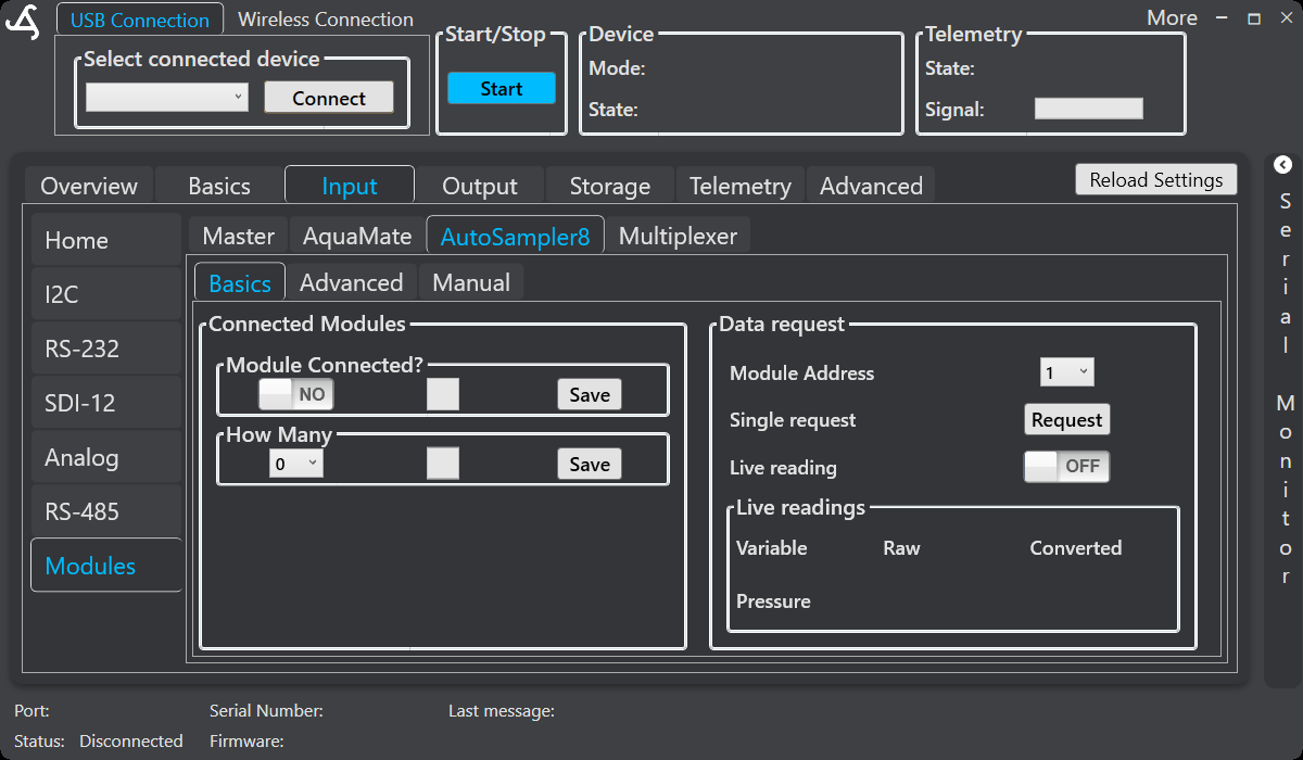
Connected modules
Use Module Connected? to indicate whether an AutoSampler8 module is installed. Use How Many to select the number of connected modules, then select the corresponding Save button.
Data request
In the Data request section:
- Select a Module Address.
- Select Request for a single data request.
- Turn Live reading on to request continuous updates, where supported.
Returned values appear in the Live readings table. The table can show the variable name together with Raw and Converted values when those values are available.
Advanced
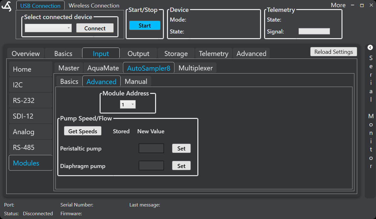
The Advanced tab contains AutoSampler8-specific configuration and calibration controls. Change these settings only when required for the connected installation, and verify the result before deployment.
Supported controls can include selecting the module address, reading and setting stored pump-speed values, and entering calibration points. For calibration, select the point, enter the measured real value, save the point, and apply the calibration. Pump-speed and calibration changes affect module operation.
Manual
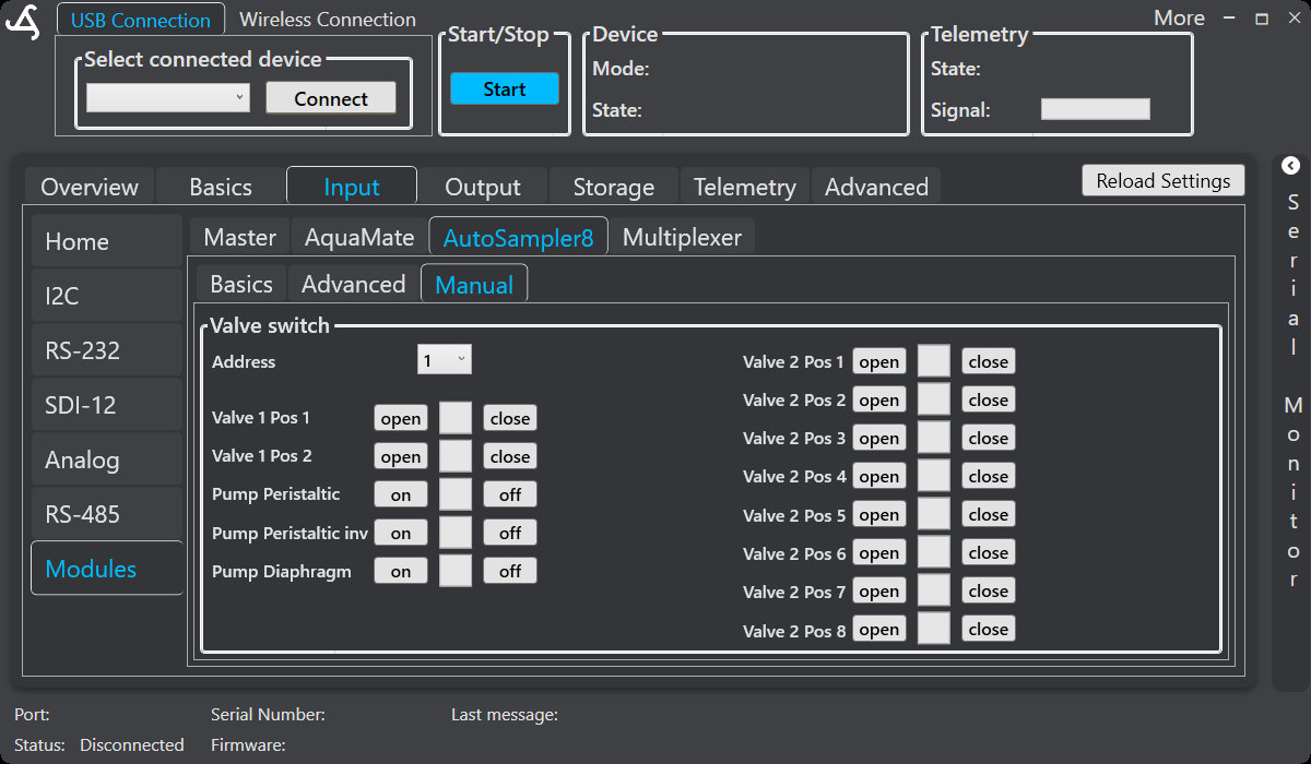
The Manual tab provides direct control of supported AutoSampler8 valves and pumps. Select the module address, then use the available controls for valve positions, the peristaltic pump, and the membrane pump.
Manual control bypasses normal automation logic. Stop or suspend an automated program before testing, and confirm that tubing, containers, and discharge paths are correctly connected.
Multiplexer
The Multiplexer tab provides Basics and Manual sections for supported multiplexer modules.
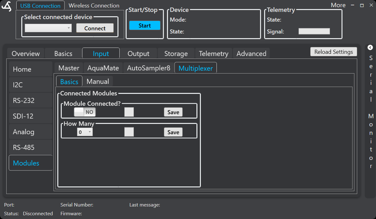
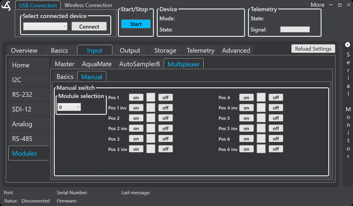
Select the module in Module selection. The manual screen provides on and off controls for positions 1 through 6 and separate controls for each position's inverted output. Use these controls for supported testing and maintenance after connecting to the SmartSampler2 and confirming the intended hardware response.
Module communication
Module requests are handled sequentially. If a request does not complete, check the physical connection, the configured module quantity, the selected address, and whether another module is using the same address. The Serial Monitor can help inspect communication and diagnostic responses.
Notes
- Only supported and enabled module interfaces appear as usable controls.
- Changing module presence, quantity, or addressing can affect module communication and the active input configuration.
- Live readings, maintenance actions, calibration, and manual controls are intended for setup, diagnostics, or controlled service work.
- Do not change wiring while equipment is powered.
- Confirm that valves, pumps, sample containers, and discharge paths are in a safe state after testing.
Related hardware: SmartSampler2 hardware reference.
Related hardware: SmartSampler2 hardware reference.