
7. Diagnostics & Troubleshooting
Before troubleshooting
Stop an automated sampling program before changing module, valve, pump, output, or communication settings. Begin with the physical checks in the verified SmartSampler2 Diagnostics & Maintenance documentation. Check power, connectors, wiring, tubing, sealing, and the operating environment before investigating configuration.
1. Check the connection and status
- Confirm that SmartSampler2 is powered and connect to the intended device in SmartConfig2.
- After connection, allow SmartConfig2 to retrieve the device settings automatically. Use Reload Settings only if automatic retrieval did not complete or you need to refresh the displayed configuration.
- Review the top status areas and the status bar. They show connection information, sampler state, telemetry state where available, the last message, and supported device or firmware information.
- If the interface does not update, reconnect the USB connection and reload the settings. Progress indicators are cleared when a settings write or reload begins, providing visible feedback that the command has started.
During an automated sequence, the sampler status can identify stages such as warming up, operating, or reporting an error. A configuration check failure prevents normal operation and requires the configuration to be reviewed before retrying.
2. Use Advanced diagnostics
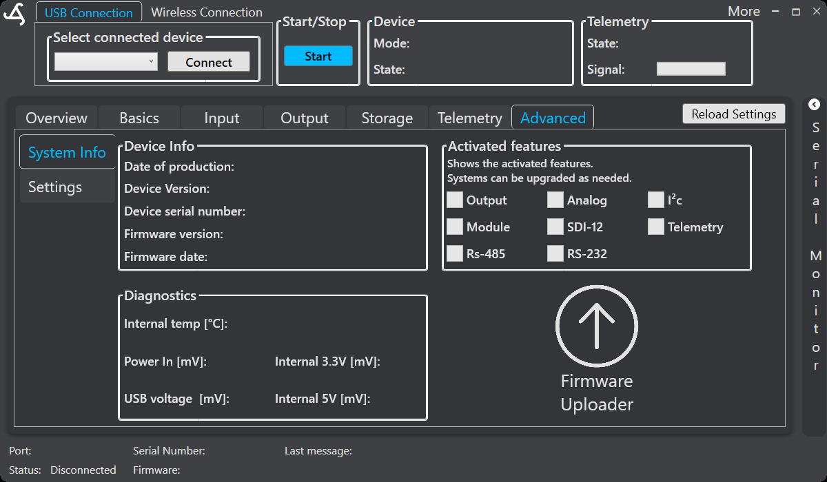
Open Advanced > System Info to review the device information, activated features, firmware information, and diagnostic readings. Available readings include internal temperature and supported supply-voltage values. A missing feature or unavailable reading may indicate licensing, configuration, power, or communication conditions.
SmartSampler2 records configuration-related information and diagnostic or error information in local storage. These records, together with the last message shown by SmartConfig2, can help distinguish a settings problem from a connected-sensor or module problem. The Advanced area also provides supported settings import, export, reset, and firmware-maintenance controls.
3. Modules, valves, pumps, and outputs
For an expansion that does not respond, verify its configuration, address, power, cabling, and connectors. Send one supported request and review the response before enabling continuous readings. Module commands are handled sequentially and unsuccessful communication may be retried; allow the request to complete before starting another test.
Use the available manual controls for controlled testing. For AquaMate, test manual valve controls carefully. For AutoSampler, use the Manual area to test supported valves and pumps one at a time. Do not operate a pump or valve when the fluid path is blocked.
SmartConfig2 can display supported output-port status and switch supported outputs on or off. Check polarity, output selection, and configured output behavior if an output appears reversed or inactive.
4. Flow and calibration problems
- Confirm that the flow-control pod and fluid path are connected correctly.
- During a controlled fill, check whether flow pulses, flow rate, and accumulated volume change as expected.
- For a volume-based fill, verify the trigger volume and confirm that filling stops at the target.
- For a supported sensor, select the correct calibration variable and point, enter the measured reference value, save the point, and apply the calibration.
- If readings remain incorrect, reset the calibration where that control is available and repeat the procedure with a verified reference.
5. Serial and sensor communications
RS-485 and Modbus
Verify the baud rate and serial format, load the intended Modbus configuration, and send one request. A request that exceeds the communication timeout is marked as failed while the remaining configured requests continue. SmartSampler2 validates received RS-485 responses before accepting them; invalid, incomplete, mismatched, or corrupt responses are rejected.
Use the manual request control when available to test one configured request. Review both the raw response and the interpreted result, including any configured scaling or offset. Repeated failures should be investigated by checking address, wiring, termination, power, and instrument configuration.
SDI-12
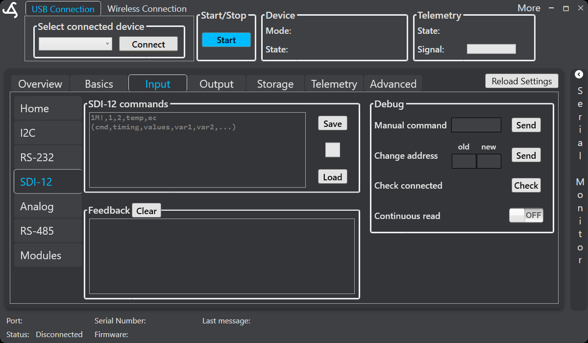
Open Input > SDI-12. The screen provides a command editor with Save and Load, a Feedback area, and Debug controls for a manual command, address changes, checking connected sensors, and continuous reading. Send one command at a time and review the result in Feedback. Use Clear before a new test when necessary.
RS-232 and UART
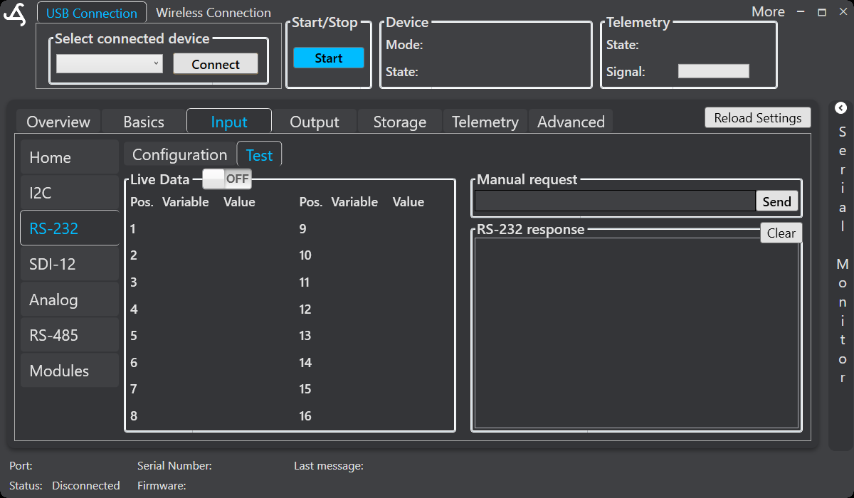
For missing or incorrectly parsed serial data, verify the baud rate, serial framing, terminator, delimiter, and variable positions for the selected interface. On Input > RS-232 > Test, use Live Data to view parsed variables, or enter a supported manual request and select Send. Review the returned text in the response area and use Clear when required.
SmartConfig2 supports configuration and live monitoring for the supported UART interfaces. Variable definitions can be loaded from or saved to SmartSampler2 storage. Enable continuous monitoring only after the serial settings match the connected instrument.
6. SD-card data transfer
SmartSampler2 stores sensor data and configuration-related information on SD-card storage. In SmartConfig2, open the Storage area, select the required file, choose a destination, and start the download. Supported save formats include TXT and CSV. SmartConfig2 displays transfer progress as a percentage.
If the card or selected file cannot be opened, SmartConfig2 reports an error. USB file transfers use acknowledged chunks and may retry a chunk when an acknowledgement is not received. Allow the transfer to finish before disconnecting USB power.
7. Telemetry and remote diagnostics
When telemetry is enabled and connected, SmartSampler2 queues outgoing messages and can send live operating information. SmartConfig2 can display supported device information, voltage readings, GPS information, connection state, and diagnostic values received remotely. Unsupported or duplicate remote messages are ignored so that the displayed information is not processed repeatedly.
Telemetry diagnostics can include recent cellular communication errors and the operating context associated with a failed communication. Review the telemetry connection status, provider settings, server settings, and error information in the Telemetry area before repeating a connection test. SmartSampler2 also attempts supported timeout recovery and reconnection when a cellular operation does not respond.
8. User-defined program issues
Validate the action order and test the program with a stopped or isolated output path first. Supported program actions include delays, waiting for the next alarm, switching modules or sensors, switching outputs, reading sensors, sending data or custom values through telemetry, sending a clean command, setting or ending a subprogram, calculating a formula, comparing values, controlling pulse flow, and using temporary storage.
A formula can calculate a runtime value from current sensor data and use the result in a later operation, including timing or fill control. Validate required parameters, program sections, comparison paths, and jump targets before running an unattended program.
9. LED and hardware indications
Use the SmartSampler2 status LED together with SmartConfig2 messages:
- Off: no power is indicated.
- Steady on: powered and in configuration mode.
- Slow blinking: normal working operation.
- Fast or continuous blinking: an error condition; check configuration, wiring, and connected loads.
The LED can be disabled through system configuration. For power, fuse, wiring, thermal, cleaning, sealing, and water-ingress guidance, follow the verified SmartSampler2 Diagnostics & Maintenance instructions.
10. Application errors
If SmartConfig2 encounters an unexpected application error, it displays an Unexpected error dialog with an error message. Record the message, the operation being performed, the connected hardware, and the steps that reproduce the problem. Restart SmartConfig2 and repeat the test only after recording this information.
11. When to contact support
Contact support when the issue persists after checking power, wiring, connectors, configuration, and the relevant live response. Include the SmartSampler2 device information shown in SmartConfig2, operating mode, connected expansion, observed status, diagnostic message, and reproducible steps. Do not continue operating equipment showing water ingress, damaged wiring, overheating, or repeated power faults; follow the verified hardware service guidance instead.