
4.2.4 Analog / Pulse / UART
Analog / UART input configuration
SmartConfig2 configures six shared signal channels on the SmartSampler2 Analog / UART connector. Each channel can be assigned as an analog input, pulse input, or as part of UART 1, UART 2, or UART 3. Connect to the SmartSampler2 first and allow SmartConfig2 to retrieve the device settings automatically. Select Reload Settings only when automatic retrieval did not complete or when you explicitly need to refresh the settings.
For connector pin assignments, electrical characteristics, signal limits, protection information, and wiring guidance, see the SmartSampler2 Analog hardware documentation. Follow that hardware documentation when connecting sensors or serial devices.
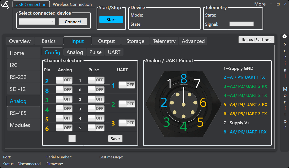
The Input area contains the navigation buttons Home, I2C, RS-232, SDI-12, Analog, RS-485, and Modules. When Analog is selected, the page provides the Config, Analog, Pulse, and UART tabs.
Config
Use the Config tab to assign the shared channels:
- Analog enables a channel for voltage measurement.
- Pulse enables a channel for pulse detection.
- UART 1, UART 2, or UART 3 reserves the corresponding TX and RX channel pair for serial communication.
The page displays the connector pinout alongside the channel switches. A channel assigned to UART cannot also be used as an analog or pulse input. Select Save in the channel-selection panel to transfer the configuration to the SmartSampler2.
The six signal channels are shared as shown in the hardware reference. The available controls can also depend on the connected hardware and enabled configuration.
Analog
Use the Analog tab to calibrate and inspect an enabled analog channel. Select a channel from the Channel list. The calibration panel provides three points—low, mid, and high—with a voltage field and a corresponding value field for each point. Enter known reference points from the sensor’s operating range. The configured calibration is used to convert the measured signal into the displayed and recorded unit value.
Select Load calibration to apply available calibration data. SmartSampler2 uses configured calibration during analog reading; the device also applies its supported input sampling and calibration processing.
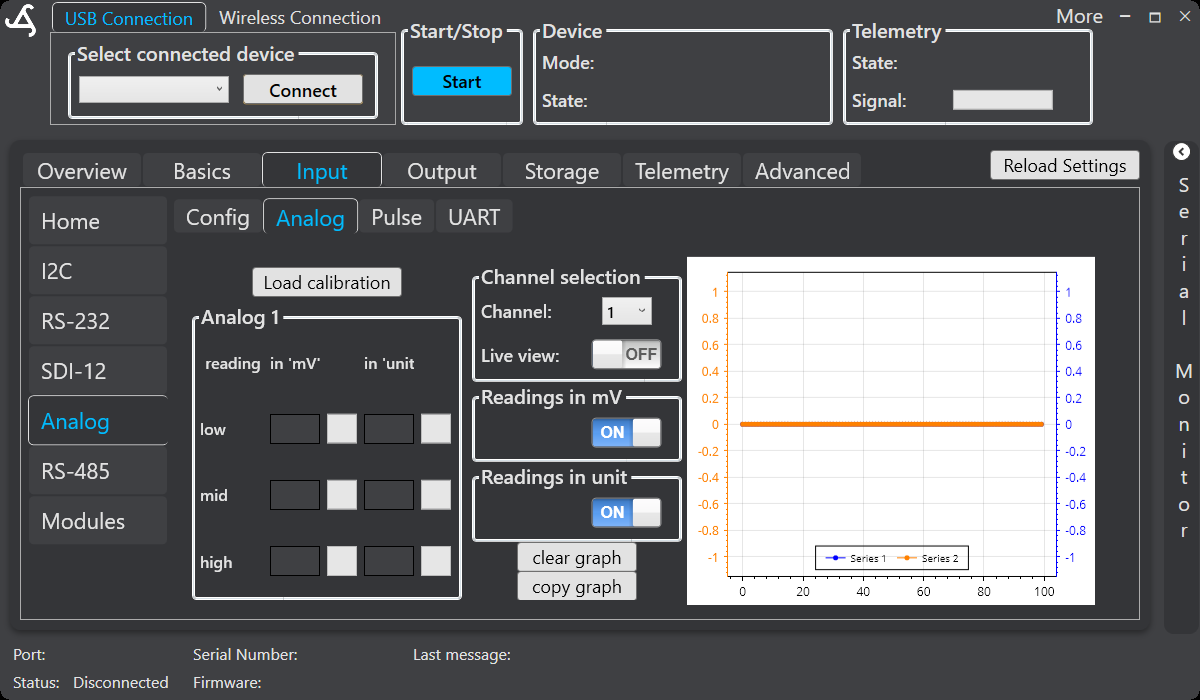
To inspect a signal, select Live view. Use Readings in mV and Readings in unit to choose which reading series appear in the graph. Clear graph removes the displayed points, and Copy graph copies the graph for documentation or analysis. Live viewing is intended for setup and verification; turn it off after testing.
Pulse
Use the Pulse tab to configure and test pulse channels. Select a channel from the Channel list, then enable Pull-Up when the connected sensor requires an internal pull-up. Default leaves the input at its default configuration. Select Save to transfer the pulse pin settings.
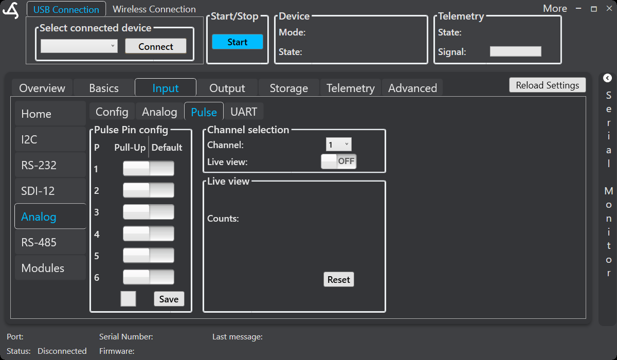
Enable Live view to monitor the selected channel’s Counts value while checking wiring and signal detection. Select Reset to clear the displayed count during testing. Pulse performance depends on the signal and wiring; consult the SmartSampler2 Analog hardware documentation for supported signal guidance.
UART
The UART tab configures three serial interfaces: UART 1, UART 2, and UART 3. Select the interface tab that matches the channel enabled on the Config tab.
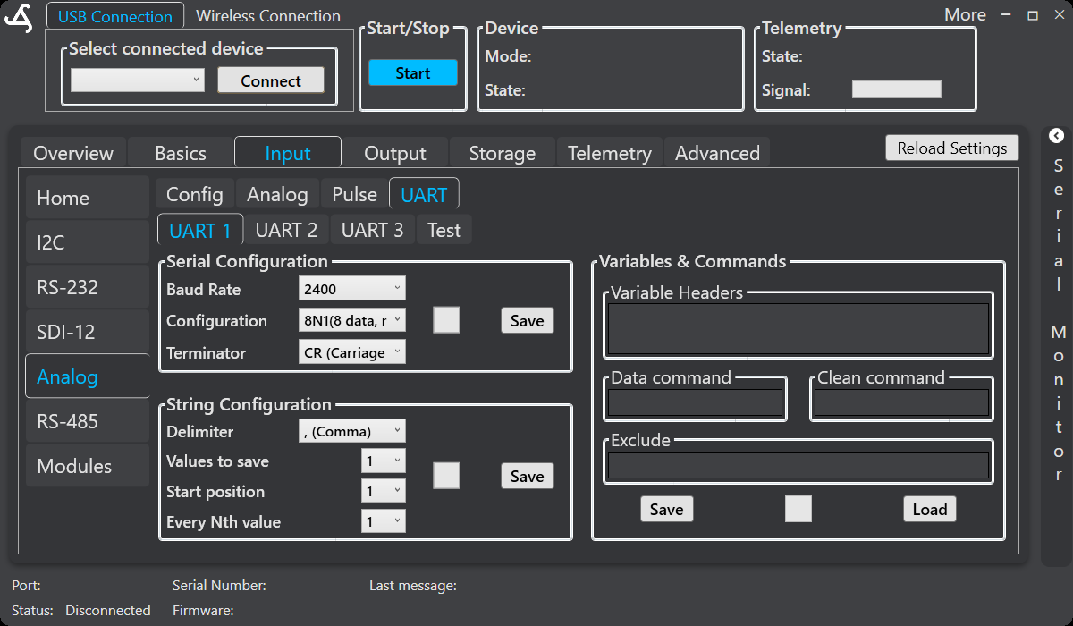
Serial configuration
Match the connected device’s communication settings:
- Baud Rate selects the communication speed.
- Configuration selects the data bits, parity, and stop bits.
- Terminator selects the message ending, such as CR, NL, or CR+LF.
Select the corresponding Save button to store the serial settings.
String configuration
Use the string settings to extract values from delimited messages:
- Delimiter identifies the separator between fields.
- Values to save sets how many values are retained.
- Start position selects the first field to retain.
- Every Nth value sets the interval for selecting subsequent fields.
Variables and commands
Use Variable Headers to name or identify returned values. Enter a Data command when the sensor requires a request for a measurement. Enter an optional Clean command for a device cleanup or reset request, and use Exclude to remove unwanted text from an incoming message.
Select Save to store the variable definitions on the SmartSampler2, or Load to retrieve saved definitions. Configured UART values are included with the other enabled sensor data and therefore contribute fields to the device’s recorded data header.
UART Test
Select the Test tab to check communication and parsing without starting normal unattended operation.
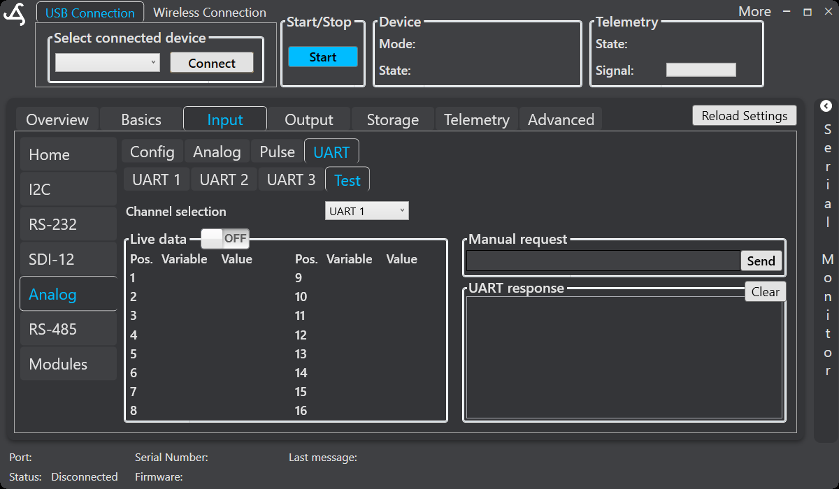
Select a UART channel and enable Live data to view parsed variables and values. To send a device request, enter it in Manual request and select Send. Review the returned text in UART response; select Clear to remove the displayed response.
Use the Test tab to verify the serial settings, terminator, request, and parser configuration. Disable live monitoring and finish saving the required settings before placing the SmartSampler2 into unattended operation.
Recommended workflow
- Connect SmartConfig2 to the SmartSampler2 and allow the settings to load automatically.
- Open Input > Analog > Config and assign the required Analog, Pulse, or UART channels.
- Select Save, then configure the relevant Analog, Pulse, or UART tab.
- Use live viewing or the UART Test tab to verify wiring and returned data.
- Turn off diagnostic live views and confirm the saved configuration before normal operation.
Related hardware: SmartSampler2 Analog hardware reference.