
4.2.2 RS-232
Use Input > RS-232 to configure serial communication between SmartSampler2 and a connected sensor or module. Connect to SmartSampler2 first. SmartConfig2 normally retrieves the device settings automatically; use Reload Settings only if retrieval did not complete or you explicitly need to refresh the displayed configuration.
Before connecting equipment, check the connector and interface information in the SmartSampler2 hardware interfaces documentation. Confirm the connected device's communication requirements in its own documentation.
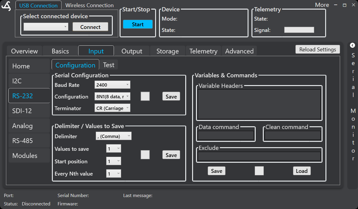
Configuration
The Configuration tab contains separate sections for serial communication, message parsing, and variable or command definitions.
Serial Configuration
- Baud Rate: Select the communication speed required by the connected device.
- Configuration: Select the serial framing, including data bits, parity, and stop bits. For example,
8N1means 8 data bits, no parity, and 1 stop bit. - Terminator: Select the line ending that identifies the end of an incoming message: carriage return, new line, or carriage return plus new line, as provided by the device.
- Select the section's Save button to store these settings in SmartSampler2.
Delimiter and values to save
SmartSampler2 receives complete serial messages, separates them into fields, and selects the fields that become sensor values.
- Delimiter: Select the character separating fields, such as a comma, semicolon, or tab.
- Values to save: Select how many values to retain.
- Start position: Select the first field to consider. Positions are counted from the left.
- Every Nth value: Select the interval between retained fields. Use
1to retain every field. For alternating name-and-value messages, use2when that matches the device output. - Select the section's Save button to store the parsing settings.
For example, for Variable1,value1,Variable2,value2, select the value fields with an interval of 2. For value1,value2,value3, use an interval of 1 to retain all fields.
Variables & Commands
- Variable Headers: Enter variable names in the order of the retained values. For example,
pH,pH_mV,tempmaps6.5,-12,21.3topH,pH_mV, andtemp. Use unique names. - Data command: Enter the request string that obtains an updated reading when the connected device requires one.
- Clean command: Enter a cleanup request when supported by the connected device.
- Exclude: Enter text identifying messages to ignore, such as startup messages or repeated headers. Matching messages are not added to the collected data.
- Select Save to store the variable and command definitions, or Load to retrieve the previously stored definitions.
During sensor updates, configured RS-232 data is parsed and added to SmartSampler2 sensor data. The configured variable names are also used in generated data headers for logging and transmission.
Testing the connection
Open the Test tab after configuring the interface. Connect to SmartSampler2 before testing; the supplied view shows the interface disconnected.
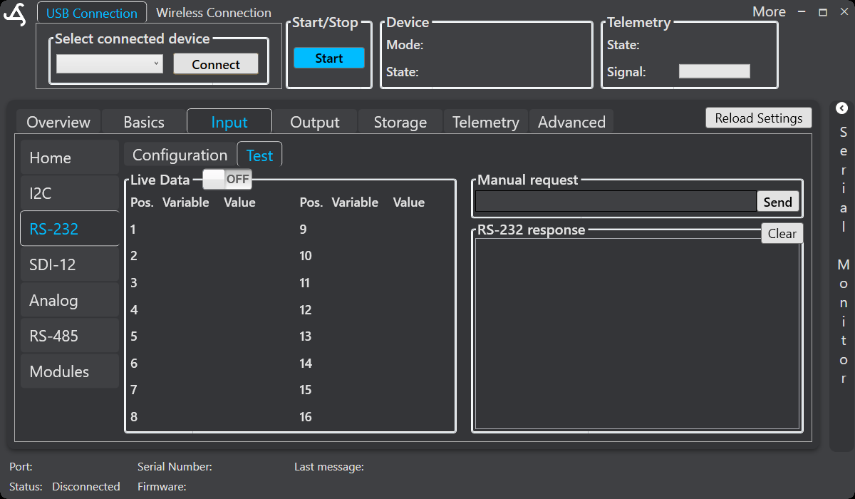
Live Data
Enable Live Data to view parsed variables and values. The table shows the configured positions, variable names, and current values as messages are received and parsed using the saved terminator, delimiter, start position, and interval.
For example, with pH,pH_mV,temp and the message 6.7,-15,21.3, the table can show pH = 6.7, pH_mV = -15, and temp = 21.3.
Manual request and response
- Manual request: Enter a device-supported request and select Send.
- RS-232 response: Review the returned response in this area.
- Clear: Remove the displayed response when required.
Use manual requests to confirm that the device responds before enabling live readings. If the response is missing or cannot be parsed, check the wiring, baud rate, serial framing, terminator, delimiter, and message format against the connected device's documentation.
Recommended workflow
- Connect SmartConfig2 to SmartSampler2 and allow the device settings to load.
- Confirm the sensor's serial settings and message layout.
- Configure the baud rate, serial framing, and terminator, then select Save.
- Configure the delimiter, values to save, start position, and every-Nth-value setting, then select Save.
- Enter variable headers and any required data, clean, or exclusion settings, then select Save.
- Open Test and send a manual request to inspect the response.
- Enable Live Data and confirm that the expected variables and values appear.
- Save the completed configuration before using the channel during normal sampling.
Related serial interfaces
The same serial parsing approach is available for supported UART interfaces. SmartSampler2 supports RS-232 and three configurable UART interfaces where provided by the installed hardware and configuration. UART settings and variable definitions are configured separately. RS-485 is configured in its dedicated Modbus area because it is intended for RS-485 bus communication.
Serial pass-through is a separate operating mode for supported serial interfaces. Use it only when required by the connected equipment and follow the confirmation and on-screen instructions in SmartConfig2.
Related hardware: SmartSampler2 hardware reference.