
4. Configuration Area
4. Configuration Area
The Configuration Area is the main workspace for viewing and changing SmartSampler2 settings in SmartConfig2. The application organizes configuration into Overview, Basic, Input, Output, Storage, Telemetry, and Advanced.
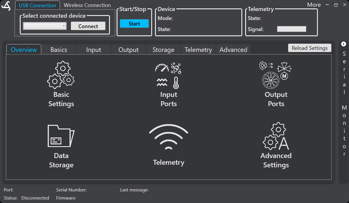
Overview
Overview presents large navigation buttons for the main configuration areas. Select a button, or use the tabs across the top of the workspace, to open the required area:
- Basic → Configure sampler operation and basic timing.
- Input → Configure and monitor supported sensor and communication inputs.
- Output → Configure and test supported controlled outputs.
- Storage → Work with data and supported device-storage functions.
- Telemetry → Configure telemetry and review connection information.
- Advanced → Manage system settings, diagnostics, settings transfer, and supported maintenance functions.
Normal connection workflow
- Connect the SmartSampler2 to the computer using the supported USB connection, or use the supported wireless connection through the installed LTE telemetry module and MQTT broker. For wireless access, use the connection details provided for your device; do not share credentials.
- Select the intended SmartSampler2 in the connection area and select Connect.
- Allow SmartConfig2 to retrieve the device configuration automatically.
- Open the required configuration area and review the values before editing.
- Save changed settings with their associated save control and wait for the completion feedback.
- Use the Status Bar and the relevant monitoring controls to confirm the connection and device response.
Select Reload Settings only when automatic retrieval did not complete or when you explicitly need to refresh the configuration shown by SmartConfig2.
Working with interfaces and data
The Input area provides pages for supported interfaces including I2C, RS-232, SDI-12, Analog, RS-485, and Modules. Depending on the interface, SmartConfig2 can provide configuration, live readings, manual requests, calibration, or pass-through controls. For example, the Analog monitor provides channel selection, calibration loading, live view, selectable reading series, and graph controls.
The Output area provides controls for supported outputs used by SmartSampler2 programs and connected equipment. Review the applicable SmartSampler2 Hardware Interfaces guidance before connecting or testing external equipment.
The Storage and Telemetry areas provide controls for supported local data and telemetry functions. SmartSampler2 can maintain configuration, raw data, historical transfer data, interface records, firmware-update records, and error information. Availability of individual records depends on the controls provided in the current SmartConfig2 interface. Averaged data and averaging workflows are not part of the current documented configuration.
Use Advanced settings for system configuration, supported power-management options, settings import and export, reset controls, and device maintenance functions. For physical inspection, power, wiring, cleaning, and water-ingress checks, follow SmartSampler2 Diagnostics & Maintenance.
Related hardware: SmartSampler2 hardware reference.