
5.1.14 Function Reference
A SmartSampler2 user-defined program is an ordered sequence of actions. SmartConfig2 lets you create that sequence in the Visual Programmer or review and edit the line-based program in Basics > Program. Configure an action by selecting its block and opening its editor, or by editing the corresponding program line. The ordered instruction list is the representation applied to SmartSampler2.
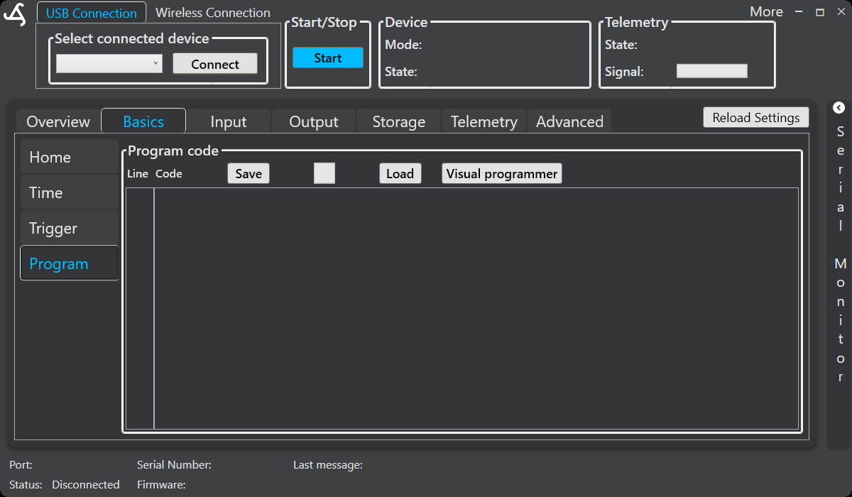
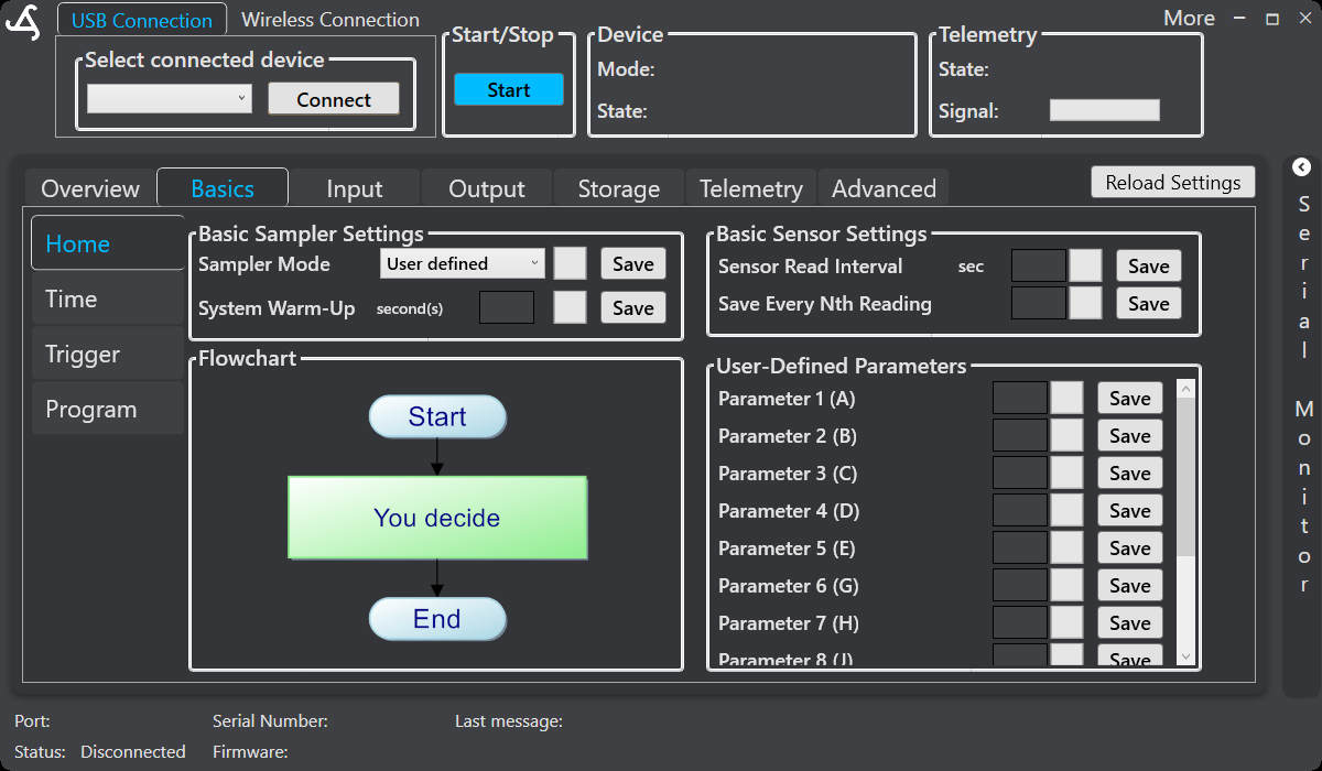
Use the Visual Programmer to build program flow, the validation tools to find configuration errors, and Simulation to investigate supported timing, formula, storage, counter, and subprogram behavior before applying the program.
Available actions
The action names shown in SmartConfig2 are:
- End program and Jump to line
- Delay and Wait for next alarm
- Switch module, Switch sensors, and Switch output
- Read sensors
- Send data, Send custom value, and Send clean command
- Set subprogram and End subprogram
- Calculate formula and Temporary storage
- Compare, Set pulse counter, and Flow control
- AquaMate command, AutoSampler8 command, and Multi-relay command, when the corresponding supported module is available
The Inspector or action editor displays only the parameters applicable to the selected action. Optional parameters can be left empty when the editor permits this.
Parameters and runtime values
Parameters are identified by letters. Their meaning depends on the action.
| Parameter | Use |
|---|---|
T | Time, operation mode, or another action-specific value. |
S | State, value, target, prefix, or comparison value. |
O | Output, storage location, pulse counter, or another action-specific selection. |
I | Optional signal state, telemetry interval, or subprogram activated by a comparison. |
P | Optional program-section number. Instructions assigned to the same P value belong to that subprogram. |
Supported value selectors can use fixed numbers or runtime values. These include sensor-data inputs, user-defined parameters, temporary storage, pulse counters, and the previous formula result. In formula expressions, the documented names include:
a–dfor the four selected sensor-data positions;A–Dfor the corresponding formula input values;G–Nfor configurable global values where provided by the configuration;U–Zfor temporary runtime storage or counter values, depending on the action;Rorrfor the previous formula result.
SmartConfig2 provides descriptive names in value selectors where available, such as a user-defined parameter, temporary value, counter, or formula result. The available choices depend on the selected action.
Program flow and timing
End program
Ends the user-defined program. The program must contain an end-program action; validation reports an error when it is missing.
Jump to line
Continues execution at a connected block or at a fixed or dynamic target. In the action editor, choose either Connected block or Line number / parameter / counter. A dynamic target can use a supported runtime value.
Delay
Waits for the specified number of seconds. Enter a fixed value or select a supported runtime value. A value of zero can use the previous formula result where the editor documents that behavior.
Wait for next alarm
Pauses execution until the next configured sampler alarm. An optional program-section value can associate the action with a subprogram.
Hardware and sensor actions
Switch module
Switches the connected module off or on, or resets it when using SmartSampler2 firmware 0.4.0 with SmartConfig2 0.3.1. The action can include an optional wait value.
Switch sensors
Switches the configured sensors on or off. Use the sensor configuration in SmartConfig2 to define the sensors and their read settings before using this action.
Switch output
Switches a SmartSampler2 output. The current action editor supports an output selection, on/off state, optional wait value, and optional signal-pin state. Output behavior depends on the configured SmartSampler2 output hardware. Do not use this reference to infer electrical ratings, pin assignments, or load limits; follow the verified SmartSampler2 hardware interfaces documentation.
Read sensors
Reads the configured sensors for the specified time. The measurement setting determines whether the reading is saved or discarded. The editor can also provide an optional send-via-telemetry interval. The save interval configured in SmartConfig2 determines how often sampled readings are written to storage; SmartConfig2 does not provide an averaging workflow.
Data, telemetry, and cleaning
Send data
Sends the latest received sensor data. An optional telemetry prefix can be supplied where shown by the editor. Configure and verify telemetry separately in the Telemetry settings.
Send custom value
Sends the current formula result, represented by r, as a custom telemetry value. The action requires a telemetry prefix and provides a message or variable field in its editor.
Send clean command
Sends the cleaning command to the configured sensors and waits for the specified cleaning time. Confirm that the connected sensors support the cleaning operation before using it.
Subprograms and comparisons
Set subprogram
Activates the subprogram identified by I. Assign the matching P value to the instructions that belong to that subprogram. A subprogram number must be in the supported range shown by the editor.
End subprogram
Ends the active subprogram. Select one of the following modes:
| Mode | Behavior |
|---|---|
| Return to caller | Returns to the instruction that activated the subprogram. |
| Continue with next block | Continues through normal Code flow. |
| Jump | Continues at the configured connected block or fixed/dynamic target. |
Compare
Compares a left value with a right value using equal to, greater than, less than, not equal to, greater than or equal to, or less than or equal to. When the comparison is true, parameter I activates the matching subprogram. Execution otherwise continues through normal Code flow.
Compare does not create separate firmware Yes and No branches. In the Visual Programmer, use normal Code flow for the physical instruction order and configure the subprogram membership for the instructions that should run when the comparison is true.
Formulas and storage
Calculate formula
Evaluates a mathematical expression using up to four selected fields from the latest comma-separated sensor-data string. Assign positions to a, b, c, and d; positions are one-based, and 0 marks an unused input. If a selected position is outside the available data range, that formula input is treated as zero.
For example, a formula action can be represented as F14,a*1,6,0,0,0. The exact fields and editor layout are shown in the formula action editor. Enter the expression in the Formula field, set the four data positions, and select Test formula to review the resolved inputs and result. SmartConfig2 reports the location and message for an invalid expression or position before the configuration is accepted.
Supported expressions include parentheses, unary signs, arithmetic operators, remainder, exponentiation, constants such as pi and e, supported runtime variables, and documented single-argument mathematical functions. Commas separate program fields and must not be used inside the formula expression.
The result is available as r or R to later actions, including a delay, comparison, storage update, output selection, flow-control target, or custom telemetry value.
Temporary storage
Modifies one of the temporary values U–Z. Select an operation such as reset, increment, decrement, or set to a fixed or supported runtime value. The action editor maps the storage selection to the corresponding temporary value.
Counters and flow control
Set pulse counter
Resets, increments, decrements, or sets a selected pulse counter. The supported pulse-counter selection and value fields are displayed by the editor.
Flow control
Waits for a selected pulse counter to reach its target, subject to the configured maximum time, and then continues through normal Code flow. Supported flow-control workflows can use pulse counts to control filling and stop when the configured target volume is reached. Flow behavior depends on the connected module, sensor, signal, and SmartSampler2 configuration.
Before wiring or commissioning a pulse source, follow the verified SmartSampler2 hardware interfaces documentation. For expansion-module connection and supported module use, see the verified SmartSampler2 expansions documentation.
Connected-module commands
When the required module configuration and hardware are available, user-defined programs can send commands to supported AquaMate, AutoSampler8, and Multi-relay modules. The action editor displays the parameters for the selected command.
- AquaMate command: selects the module address and module-dependent position or output, together with the available state or command.
- AutoSampler8 command: provides the module address, task, position or output, and task-dependent state.
- Multi-relay command: provides the module address, output or position, and available relay action or state.
Only use module commands with compatible connected hardware. The verified SmartSampler2 expansions documentation describes module connection guidance; it does not change the electrical ratings or safety instructions for SmartSampler2.
Recommended workflow
- Connect SmartConfig2 to SmartSampler2 and allow the device settings to load automatically.
- Select User defined as the sampler mode in Basics > Home.
- Configure the sensor read interval, save interval, user-defined parameters, and any required module or telemetry settings.
- Open Basics > Program and select Visual programmer, or work directly with the line-based program.
- Add the required actions and configure each block in its editor.
- Connect blocks with Code flow. Configure jump targets, subprogram membership, comparisons, and returns according to the required runtime behavior.
- Validate the program. Correct missing end-program actions, unsupported parameters, invalid ranges, invalid placeholders, formula errors, and missing subprogram references.
- Use Simulation where supported to check formulas, runtime values, timing, counters, storage, and flow behavior.
- Apply the validated program to SmartConfig2, review the generated program, and send the configuration to SmartSampler2.
- Use the documented diagnostic and communication tools when commissioning the connected hardware.
Program actions configure SmartSampler2 behavior but do not replace the verified hardware documentation. Always follow the SmartSampler2 hardware ratings, pinouts, protection information, and safety instructions when connecting sensors, modules, outputs, or pulse sources.
Related hardware: SmartSampler2 hardware reference.