
4.2.3 SDI-12
Use Input > SDI-12 to configure SDI-12 sensors connected to SmartSampler2. Connect to SmartSampler2 first. SmartConfig2 normally retrieves the device settings automatically; use Reload Settings only if retrieval did not complete or you explicitly need to refresh the displayed configuration.
For connector and interface information, see the SmartSampler2 hardware interfaces documentation. Confirm each sensor's address, measurement command, response format, and wiring requirements in the sensor documentation.
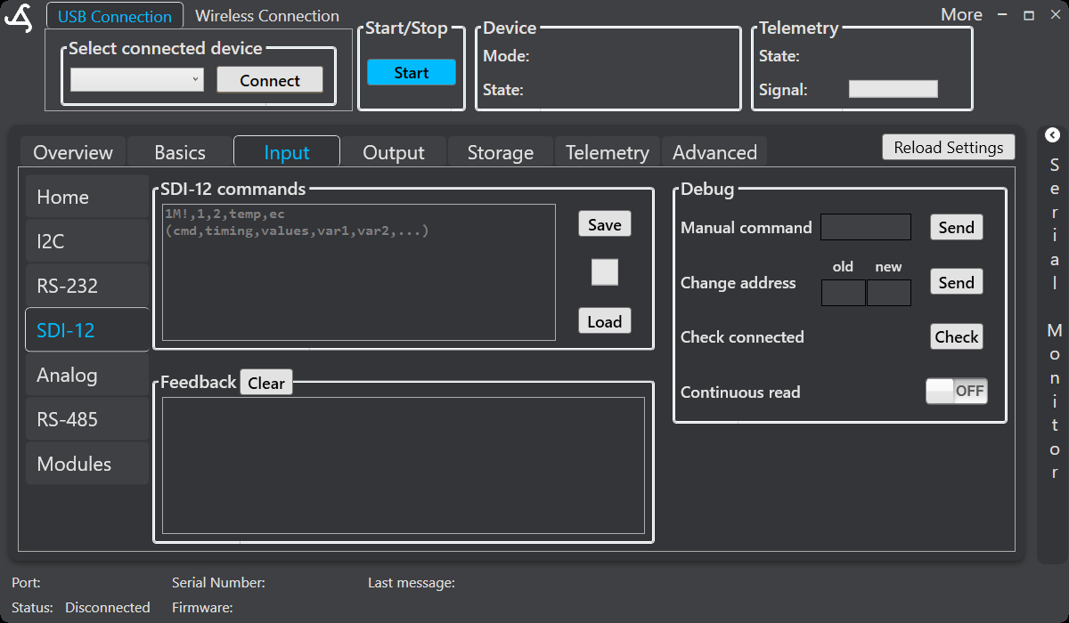
SDI-12 commands
Enter one sensor definition per line using this format:
command,update_interval,expected_values[,var1,var2,...]- command: The SDI-12 measurement command, including the sensor address. For example,
1M!requests a measurement from address1. - update_interval: The interval between scheduled requests, in seconds.
- expected_values: The number of measurement values expected in the response.
- var1, var2, ...: Optional names assigned to returned values in order.
Examples
One sensor without custom names:
1M!,10,2This requests a measurement from address 1 every 10 seconds and expects two values. SmartSampler2 assigns generic names when custom names are not supplied.
One sensor with variable names:
1M!,10,2,temp,ecThe returned values are labeled temp and ec in sensor data and generated headers.
Multiple sensors:
1M!,10,2,temp,ec
2M!,30,1,soil_moisture
Each active sensor is scheduled using its own update interval. Multiple configured sensors can be processed in turn, including concurrent measurements where supported by the sensor response.
Save and load
- Save: Stores the command definitions in SmartSampler2.
- Load: Retrieves the previously stored command definitions.
- Clear in the Feedback panel: Clears the displayed response; it does not replace the saved command definitions.
Debug tools
Use the Debug panel to check the bus and inspect sensor responses.
- Manual command: Enter a supported SDI-12 request and select Send. The response appears in Feedback. This can also be used for supported sensor-information requests.
- Change address: Enter the old and new addresses, then select Send. Use this only when supported by the sensor.
- Check connected: Select Check to probe available addresses and identify responding sensors.
- Continuous read: Enable the toggle to apply the configured command set continuously and display responses in real time. This is an isolated test mode.
- Clear: Clears the Feedback display.
If a request fails or is invalid, check the sensor address, command format, wiring, power, and sensor documentation before trying again. Returned values are included in SmartSampler2 sensor data according to the configured value count and variable names. If a response does not provide the expected number of values, the corresponding selected entries remain represented as unavailable readings rather than being silently omitted.
Recommended workflow
- Connect SmartConfig2 to SmartSampler2 and allow the device settings to load.
- Confirm each sensor's SDI-12 address and measurement command.
- Select Check beside Check connected to verify that sensors respond.
- Enter one valid definition per line, including the update interval, expected value count, and optional variable names.
- Select Save to store the command definitions.
- Use a manual command or enable Continuous read to verify the responses in Feedback.
- Confirm the values in the normal monitoring or sensor-data view before starting the operating program.
Related hardware: SmartSampler2 hardware reference.