
4.2.5 RS-485 (Modbus RTU)
SmartSampler2 supports Modbus RTU-compatible sensors through its RS-485 interface. In SmartConfig2, configure the serial connection, define the values to read, save the sensor configuration, test individual requests, and monitor returned data.
Overview
- Protocol: Modbus RTU
- Interface: RS-485, half-duplex
- Serial settings: The baud rate and serial frame format must match the connected device.
- Register requests: Requests use Read Holding Registers by default. A data request can specify function code
04when supported by the connected device. - Live Reading: Continuously polls configured Modbus values and displays the returned readings in SmartConfig2.
- Register blocks: Compatible sequential variables can be grouped into blocks for polling.
- Value conversion: Multi-register values, including four-byte values, can be decoded with a selected byte order, scaling factor, and offset.
Connect SmartConfig2 to SmartSampler2 before retrieving settings or testing a sensor. After a successful connection, SmartConfig2 normally retrieves the device settings automatically. For the electrical interface, termination, biasing, connector information, and safety requirements, see SmartSampler2 hardware interfaces.
In this article
Configuration
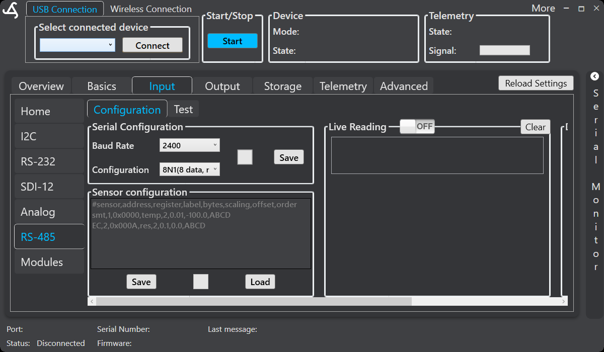
Open Input, select RS-485, and open the Configuration tab. The page contains the Serial Configuration panel, the Sensor configuration field, Save and Load controls, and the Live Reading area.
Serial configuration
- Baud Rate: Select the communication speed required by the connected sensor.
- Configuration: Select the serial frame format, including data bits, parity, and stop bits. For example,
8N1means 8 data bits, no parity, and 1 stop bit. - Save: Stores the selected RS-485 serial settings in SmartSampler2 configuration.
Sensor configuration
Enter supported Modbus definitions in the Sensor configuration field. Enter each definition on its own line. The definition identifies the device address and register data, and specifies how the returned value is converted.
| Request | Format |
|---|---|
| Measurement request | sensor_name,address,MEAS,register,value,wait |
| Data request | sensor_name,address,register,label,bytes,scaling,offset,order,function |
Parameters
- sensor_name: Group name used for the sensor data and logs.
- address: Modbus device address in decimal.
- MEAS: Identifies a measurement trigger rather than a returned sensor variable.
- register: Starting register address in decimal or hexadecimal, such as
0or0x0000. - value: Value associated with a measurement request, written in hexadecimal, such as
0x001F. - wait: Delay before the next request, in milliseconds.
- label: Name assigned to the decoded value.
- bytes: Number of bytes to read. Use
4for a four-byte value spanning two registers. - scaling: Multiplier applied to the decoded raw value.
- offset: Value added after scaling.
- order: Byte order for decoding. Supported four-byte orders are
ABCD,DCBA,BADC, andCDAB. - function: Leave blank for the default Read Holding Registers request, or enter
1to use function code04where supported by the device.
Examples
A measurement request can use the following form:
SensorName,1,MEAS,0x0001,0x001F,500
A data request can use the following form:
SensorName,1,0,temp,4,1.0,0,ABCD
Confirm the exact register map, device address, data type, byte order, scaling, offset, and supported function code in the sensor manufacturer's documentation.
Save and load
- Save: Stores the current Modbus sensor definitions in SmartSampler2 storage.
- Load: Retrieves the previously saved Modbus sensor definitions.
Live Reading
Turn on Live Reading after configuring and saving the sensor definitions. SmartSampler2 polls the configured register blocks sequentially, converts returned values using the selected byte order, scaling, and offset, and makes the decoded readings available to the SmartConfig2 live-data display and the SmartSampler2 sensor data record.
When a block does not respond before the communication timeout, that request is reported as failed and SmartSampler2 continues with the remaining configured blocks. A short delay separates successive requests.
Select Clear in the Live Reading area to remove displayed live data before starting a new test.
Test
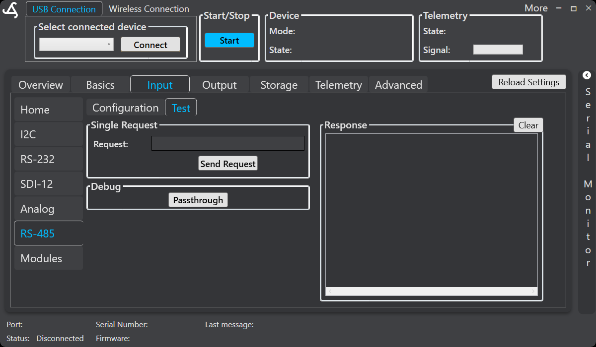
Open the Test tab to send one manual request or to diagnose the serial connection. Connect to SmartSampler2 first, then enter a supported request in Single Request and select Send Request.
Single request
- Enter one data request using the same definition format as the Sensor configuration field.
- Use the device address and register information specified by the connected sensor.
- For a four-byte value, set
bytesto4; the response then spans two registers. - SmartSampler2 checks the received Modbus response against the expected device address and function before processing it.
- The response area displays the returned response and the interpreted result when available.
Response and conversion
A manual request reports the raw response and interprets supported two-byte or four-byte values. SmartConfig2 can show the available four-byte byte-order interpretations—ABCD, DCBA, BADC, and CDAB—and applies the configured scaling and offset. Use the result to identify the byte order and conversion required by the sensor documentation.
Select Clear in the Response panel to remove the current response before another test.
RS-485 pass-through
Passthrough forwards data between the selected SmartSampler2 RS-485 interface and the USB connection without applying the configured Modbus parsing rules. Use it only for low-level troubleshooting or communication with an external tool.
Read the confirmation warning shown by SmartConfig2 before enabling this mode:
- External power is required.
- Disconnect SmartConfig2 from SmartSampler2.
- Use the same USB connection to communicate with the RS-485 or Modbus device.
- To reset SmartSampler2, fully disconnect all power.
Notes and troubleshooting
- Register addresses may be entered in decimal or hexadecimal with the
0xprefix. - Verify that the RS-485 serial settings match the sensor exactly.
- Confirm the device address, register map, register count, byte order, data type, scaling, offset, and function code in the sensor documentation.
- Use a Single Request to confirm communication and value interpretation before enabling Live Reading.
- If requests fail, check wiring and the SmartSampler2 RS-485 interface requirements in the hardware documentation.
- Readings acquired through the enabled RS-485 interface are included in the SmartSampler2 sensor data record and can be used by configured sampling workflows.