
2.1.3 Analog / Pulse / UART
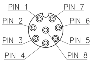
Port pinning
| Pin | Function | Pigtail wire color |
|---|---|---|
| 1 | GND | white |
| 2 | Analog/Pulse 1 / UART 1 TX (0 – 5 VDC) | brown |
| 3 | Analog/Pulse 2 / UART 2 RX (0 – 5 VDC) | green |
| 4 | Analog/Pulse 3 / UART 2 TX (0 – 5 VDC) | yellow |
| 5 | Analog/Pulse 4 / UART 3 RX (0 – 5 VDC) | grey |
| 6 | Analog/Pulse 5 / UART 3 TX (0 – 5 VDC) | pink |
| 7 | VIN, 5V or 3.3V | blue |
| 8 | Analog/Pulse 6 / UART 1 RX (0 – 5 VDC) | red |
Analog / Digital Input – Signal Characteristics
The analog inputs are designed for robust 0–5 V signals and can be used in three ways:
- Analog measurement
- Digital / pulse detection
- UART communication (logic-level)
An internal protection and filtering network improves noise immunity and protects the microcontroller input.
Supported Signal Levels
- Input voltage range: 0–5 V DC
- Signals are internally scaled and protected to safely interface with the microcontroller (3.3 V domain).
Pulse Detection (Digital Input Mode)
The analog inputs includes internal filtering to suppress noise and false triggers.
This makes it well suited for counting slow and medium-speed pulses from sensors, flow meters, reed switches, or logic outputs.
Recommended pulse frequency range
| Pulse frequency | Behavior |
|---|---|
| 0 – 1 kHz | Fully reliable, clean edges |
| 1 – 2 kHz | Typically reliable |
| > 2 kHz | Edges become increasingly rounded; reliability depends on signal quality |
Practical guidance
- For guaranteed pulse counting, keep frequencies ≤ 1 kHz.
- For higher frequencies, ensure:
- Push-pull (actively driven) signal source
- ≥ 50 % duty cycle if possible
Open-collector / open-drain sources may require lower frequencies due to slower edge rise times.
UART Communication via Analog Inputs
Analog channels can alternatively be configured as UART.
Because the input includes noise filtering, very high baud rates are intentionally not supported.
Reliable UART baud rates
| Baud rate | Recommendation |
|---|---|
| up to 38 400 | Fully reliable |
| 57 600 | Typically reliable |
| 115 200 | Possible under ideal conditions |
| > 115 200 | Not recommended |
Notes on UART usage
- Designed for robust field communication, not high-speed data streaming
- Best used with:
- Short cable lengths
- Clean logic-level signals
- Push-pull drivers
If higher baud rates are required, the other Serial interface (RS-232 / RS-485 ) are recommended.
UART wiring and loopback test
RX means receiver and TX means transmitter. Connect opposite functions: sensor TX to logger RX, sensor RX to logger TX, and connect the common GND. This port uses logic-level UART signals; do not connect an RS-232 electrical interface directly.
- Disconnect the main power supply and any external serial device. Power SmartSampler2 through USB only.
- Activate and configure the UART port that needs troubleshooting.
- Identify the dedicated RX and TX pins for that selected UART.
- Short RX directly to TX on the same port. Do not short either pin to GND or VIN.
- Open the Manual Command or Test section in SmartConfig2.
- Send a payload such as
data. - The response should appear immediately and match the request exactly:
data. - Remove the RX–TX short before reconnecting the sensor or main power.
Reliability tip: Because of the internal input protection and filtering circuits, use baud rates below 57,600 for reliable field communication.
Related configuration: 4.2.4 Analog / Pulse / UART in SmartConfig2.