
2.1.5 RS-232
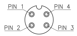
Port pinning
| Pin | Function | Pigtail wire color |
|---|---|---|
| 1 | GND | brown |
| 2 | TX (transmit) | white |
| 3 | RX (receive) | blue |
| 4 | VIN, 5V or 3.3V | black |
Important: Connect the TX (transmit) pin of one device to the RX (receive) pin of the other device, and vice versa. Do not connect TX to TX or RX to RX. Ensure that both devices share a common GND connection.
RX means receiver and TX means transmitter. The sensor and logger therefore use opposite connections: sensor TX to logger RX, and sensor RX to logger TX.
RS-232 loopback test
- Disconnect the main power supply and any external serial device. Power SmartSampler2 through USB only.
- Activate and configure the RS-232 port that needs troubleshooting.
- Identify the dedicated RX and TX pins.
- Short RX directly to TX on the same RS-232 port. Do not short either pin to GND or VIN.
- Open the Manual Command area in the SmartConfig2 RS-232 Test tab.
- Send a payload such as
data. - The response should appear immediately and match the request exactly:
data. - Remove the RX–TX short before reconnecting the sensor or main power.
Important: RS-232 and logic-level UART use different electrical signal levels. Use only the connector and interface intended for the connected device.
Reliability tip: For field troubleshooting, use a baud rate below 57,600 unless the connected instrument specifically requires a higher rate and the complete connection has been validated.
Related configuration: 4.2.2 RS-232 in SmartConfig2.