
3. Installation
3.1 Physical Mounting
- Enclosure dimensions: 192 × 112 × 65 mm.
- Weight: approximately 1.1 kg.
- Weatherproof IP67 — ensure cable glands are properly tightened.
- Small footprint suitable for backpack transport or pole mounting.
3.2 Power Supply
- Supply voltage range: 10–16 VDC.
- Maximum system power: 120 W total.
- Built-in protection: Overcurrent fuse, reverse polarity protection.
- Brownout protection and safe recovery after power interruptions.
3.3 Solar Panel, Charger, and Battery
Connect SmartSampler2 directly to the battery terminals. Do not power it from the solar charger's Load output. Some smart chargers can switch that output off because of low-current detection, protection settings, or timer modes; this behaviour has been reported with Victron MPPT chargers.
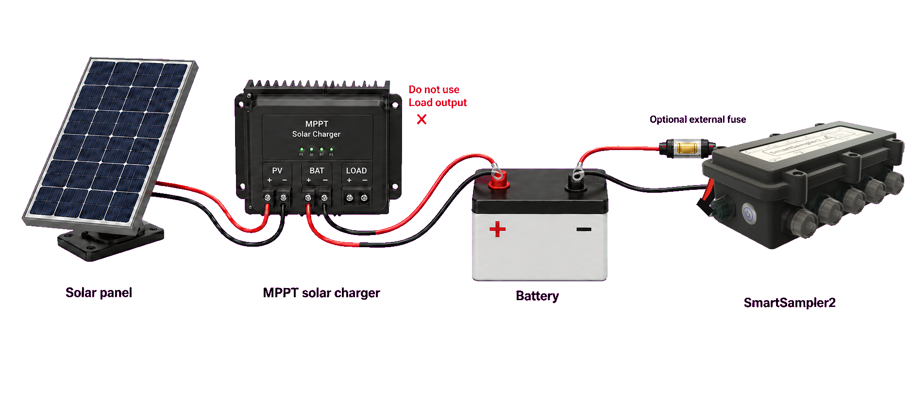
- Connect MPPT BAT + to battery + with the red conductor and MPPT BAT − to battery − with the black conductor.
- Connect SmartSampler2 directly to the same battery terminals: red to +, black to −.
- An external cable fuse is optional because SmartSampler2 has an internal fuse. An external fuse can still protect the supply cable when required by the installation.
- Use a battery and charger intended for the same battery chemistry and configure the charger correctly.
- Keep the SmartSampler2 supply between 10 and 16 VDC. SmartSampler2 does not provide overvoltage protection above its maximum input voltage.
- For lithium batteries, treat the battery-management system as emergency protection rather than the normal charge-control method. The charger must stop safely at the battery's specified maximum voltage.